

Precision Air Cooler and Components Injection Mould for Reliable HVAC Production
Admin 2026-09-22
Evaporative air coolers depend on a combination of functional internal parts, protective housings, ventilation structures, mounting features, and carefully controlled airflow passages. Although many of these components are manufactured from thermoplastics, they are not simple products to mold. Large external panels must remain dimensionally stable, fan covers require consistent ventilation openings, mounting points must withstand assembly forces, and visible surfaces need an attractive finish suitable for residential, commercial, and industrial equipment.
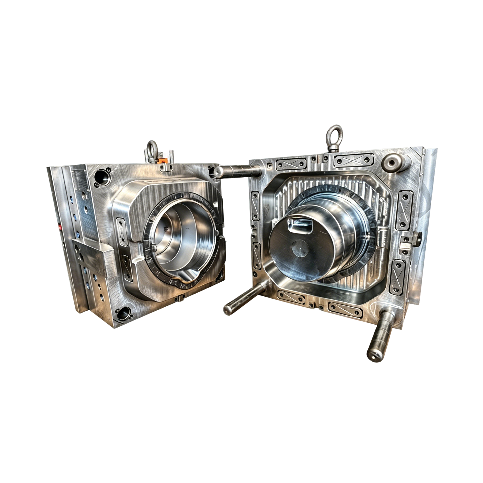
The Air Cooler and Components Injection Mould is developed for the efficient production of plastic housings and structural components used in evaporative air coolers. It supports the manufacture of air cooler housings, fan covers, cooling unit components, and related molded parts made from materials such as ABS and PP. The tooling concept is suitable for large molded surfaces with ventilation structures and integrated mounting details, while allowing component dimensions and assembly features to be adjusted for individual product requirements.
For manufacturers seeking a dependable source of plastic molding for air conditioner and air cooler products, tooling quality directly affects production cost, product appearance, assembly performance, and long-term reliability. A well-engineered mold helps reduce defects, stabilize cycle times, protect product dimensions, and maintain consistent output across hundreds of thousands of shots. The mold described in this article is designed around those production priorities.
Why Air Cooler Components Require Specialized Injection Moulds
Air coolers operate in demanding environments. Their housings are exposed to moisture, airflow, vibration, temperature changes, handling, and repeated assembly operations. The outer case must protect internal components while also allowing air to enter and exit efficiently. As a result, the molded structure often combines broad panels, ribs, louvers, openings, bosses, clips, handles, and attachment points in one component or in a coordinated group of components.
Large plastic parts create several challenges during injection molding. If the wall thickness is not balanced, the part may experience sink marks, warpage, uneven shrinkage, or visible flow lines. If the cooling system is poorly arranged, one side of the component may cool more quickly than another. If the ejection system is insufficient, the housing can deform when removed from the cavity. Ventilation grilles and narrow openings can also make filling and venting more complex.
The mold must therefore be designed as a production system rather than merely as a cavity containing the product shape. Steel selection, parting-line strategy, gate location, runner design, cooling-channel layout, ejection balance, draft angles, insert construction, and surface treatment all influence the final result. These considerations are especially important for air cooler parts because many surfaces remain visible after assembly.
The Air Cooler and Components Injection Mould addresses these requirements through a configuration intended for large housing parts, ventilation structures, and mounting features for internal components. The tooling can be adapted to the customer’s component dimensions, assembly requirements, material selection, and production plan.
Product Scope and Typical Applications
The mold is intended for the production of several categories of air cooler plastic components. The primary application is the air cooler housing, which forms the protective body around the fan, water circulation system, cooling pads, control system, and supporting frame. Depending on the product design, the housing may include side walls, rear panels, upper sections, front panels, or modular covers.
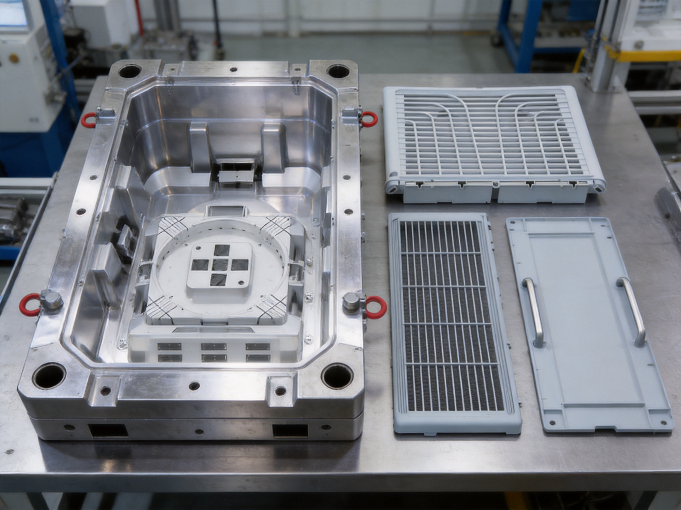
Another important application is the fan cover. Fan covers require carefully arranged openings to permit airflow while helping protect users from moving components. Their grille geometry must be consistent, strong, and visually uniform. The mold can be configured for the ventilation patterns, reinforcement ribs, attachment points, and surface appearance required by the equipment manufacturer.
Cooling unit components represent a further application area. These may include structural panels, protective covers, air-guiding elements, mounting frames, water-system covers, and other molded parts used within or around the cooling assembly. The final configuration depends on the product architecture and the customer’s design drawings.
The tooling is also suitable for customized component families. A manufacturer may require several housing sizes using similar design principles, or different versions for residential and commercial equipment. By reviewing the product structure at the beginning of the project, the mold design can be aligned with the intended assembly method, expected output, and maintenance strategy.
| Product Type | Air Cooler and Components Injection Mould |
| Main Applications | Air cooler housings, fan covers, cooling unit components |
| Typical Product Materials | ABS and PP |
| Recommended Mold Steel | 718 or NAK80 |
| Reference Mold Life | Up to 800,000 shots |
| Design Scope | Large housings, ventilation structures, mounting features, structural components |
| Customization | Component dimensions, surface details, mounting structures, and production requirements |
Advantages of the Air Cooler Housing Injection Mold
Stable Production for Large Plastic Housings
Large housings are sensitive to filling imbalance and uneven cooling. A tooling system intended for these products must control the movement of molten plastic through broad and sometimes irregular areas. Appropriate gate placement and runner balancing help the material reach critical sections with a controlled flow pattern. This reduces the risk of short shots, weld-line weakness, excessive packing, and dimensional inconsistency.
Stable production is valuable because air cooler housings are usually produced in significant quantities. A minor defect rate can result in substantial material waste, additional inspection, rework, and delayed assembly. Consistent molding allows manufacturers to plan production more accurately and reduces interruptions caused by repeated process adjustments.
Integration of Ventilation Structures
Ventilation openings are essential to air cooler performance. The grille or louver system must permit the required airflow while preserving adequate structural strength. Thin openings, repeated ribs, and closely spaced features can be difficult to fill and eject if the mold is not correctly designed.
The product tooling supports ventilation structures as part of the molded component. The layout can be reviewed according to airflow needs, appearance expectations, cleaning requirements, and structural loading. Consistent openings improve product uniformity and help ensure that assembled units present the same visual and functional characteristics throughout a production batch.
Support for Mounting Features
Air cooler housings frequently contain bosses, brackets, screw towers, clips, and locating structures. These features position fans, motors, pumps, control boards, wiring components, water tanks, and other internal assemblies. Poorly controlled mounting points can cause misalignment, difficult assembly, excessive fastening stress, or noise caused by vibration.
The mold can be customized to accommodate the required mounting structures. Their location, height, diameter, rib support, draft, and fastening method can be coordinated with the customer’s assembly drawings. This approach helps the molded part perform as an active structural element rather than as a simple decorative cover.
Suitable Surface Quality for Consumer Equipment
Air coolers are commonly installed in visible locations, so housing appearance influences the perceived quality of the finished product. The mold surface can be prepared according to the required finish, whether the design calls for a smooth surface, controlled texture, matte appearance, or selected polished areas. Correct machining and surface preparation help reduce visible tooling marks and support repeatable cosmetic results.
Surface quality also depends on the relationship between mold finish, plastic material, processing conditions, and part design. A suitable draft angle is needed to release textured areas without scuffing. Venting must be adequate to prevent burn marks and trapped-air defects. Ejection must be balanced so that the part is removed without distortion or stress whitening.
Long-Term Tooling Value
The reference mold life is up to 800,000 shots, subject to product design, material selection, processing conditions, maintenance, and operating discipline. A long-life mold provides more than a high number of production cycles. It can help distribute tooling investment across a large output volume, reduce the frequency of replacement tooling, and support stable supply for long-running product programs.
Durability depends on the complete construction of the tool. The selected steel grades, heat treatment, moving mechanisms, cooling design, wear surfaces, ejector components, and maintenance access all contribute to service life. The use of 718 or NAK80 mold steel provides a practical basis for applications requiring reliable machining quality, surface performance, and repeatable production.
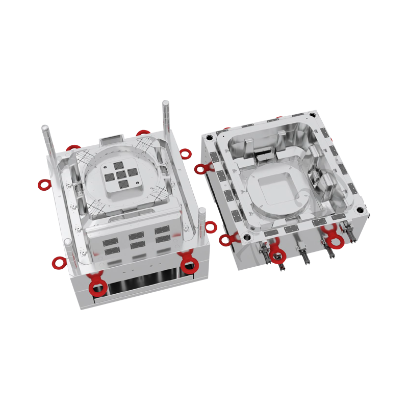
Air Cooler and Components Injection Mould
Material Selection: ABS and PP
The Air Cooler and Components Injection Mould supports ABS and PP product materials. The final selection should be made according to mechanical performance, appearance, chemical exposure, operating temperature, impact requirements, product weight, and cost targets.
ABS for Rigid and Attractive Housings
ABS is widely used for appliance housings because it offers a useful combination of rigidity, impact resistance, dimensional stability, and surface appearance. It can be molded into detailed shapes and is available in grades suitable for different performance requirements. For visible air cooler panels, ABS may be selected where a firm feel, clean appearance, and controlled surface finish are important.
When molding ABS, the processing team must consider drying requirements, melt temperature, filling speed, packing pressure, and cooling time. Moisture or unsuitable processing can affect the appearance and mechanical properties of the molded component. The mold design should include appropriate venting and cooling to help achieve consistent results over the entire housing.
PP for Lightweight and Cost-Efficient Components
PP is valued for its low density, chemical resistance, fatigue resistance, and economical processing characteristics. It can be a suitable choice for air cooler components where reduced weight, flexible clips, water exposure resistance, or cost control is important. PP may be used for structural panels, covers, internal supports, and other parts depending on the required stiffness and appearance.
Because PP has different shrinkage behavior from ABS, the mold and process must be matched to the selected resin. Product dimensions, cooling conditions, gate positions, and packing parameters should be evaluated with the chosen grade in mind. A mold intended for material flexibility should be developed from the beginning with the actual production resin and anticipated process window in consideration.
Material and Mold Compatibility
Using one mold concept for multiple possible materials does not mean that every material can be processed under identical conditions. ABS and PP differ in flow behavior, shrinkage, cooling response, and surface characteristics. The mold design should therefore be reviewed with the customer’s material selection before final steel processing.
Material compatibility also includes resistance to wear and chemical exposure. Some additives, glass fibers, flame retardants, pigments, and recycled content can influence mold wear or surface appearance. Clear communication between the product manufacturer, material supplier, and mold manufacturer helps establish appropriate steel, surface treatment, and maintenance requirements.
Advanced Mold Design and Engineering Process
Product Design Review
The manufacturing process begins with a review of the product geometry and its intended use. Engineers examine wall thickness, ribs, bosses, openings, undercuts, draft angles, parting lines, assembly interfaces, and visible surfaces. This review helps identify possible problems before steel cutting begins.
For air cooler housings, special attention is given to broad panels and transition areas. Sudden changes in wall thickness can lead to sink marks and uneven shrinkage. Large flat areas may require reinforcement ribs or controlled curvature to improve stiffness and reduce warpage. The design team can recommend modifications that preserve the product’s appearance while improving moldability.
Parting-Line Planning
The parting line defines how the mold separates and has a direct effect on product appearance, flash control, tooling complexity, and ejection. For a visible housing, the parting line should be positioned where any witness mark is acceptable or can be hidden during assembly. At the same time, the line must allow the component to release without damaging grilles, clips, bosses, or other details.
Well-planned parting lines also simplify maintenance. If inserts, sliders, or replaceable wear components are needed, their position should be accessible for inspection and replacement. A practical parting-line strategy balances product quality with tooling cost and long-term serviceability.
Gate and Runner Strategy
Injection location influences filling balance, weld-line position, packing effectiveness, cosmetic appearance, and cycle time. Large air cooler parts may require one or more gates, depending on their size and shape. Gate selection can be adapted to the product’s material, wall thickness, appearance requirements, and expected output.
The runner system should deliver molten plastic efficiently while limiting unnecessary pressure loss and material waste. Balanced flow reduces the risk that one region fills too early while another remains incomplete. For visible surfaces, gate marks can be located in less noticeable areas or on surfaces covered during assembly whenever the design permits.
Cooling System Optimization
Cooling is a major factor in dimensional stability. A housing with uneven cooling may shrink differently from one region to another, causing twist, bowing, or difficulty during assembly. The cooling-channel arrangement should follow the product geometry as closely as practical, with special attention to thick sections, bosses, rib intersections, and broad cosmetic surfaces.
Efficient cooling can also reduce cycle time. Shorter and more consistent cycles improve production capacity, although cooling should never be reduced to the point that the product is ejected before it has sufficient rigidity. The correct balance is established through product geometry, resin characteristics, mold temperature, cooling-water conditions, and machine parameters.
Ejection System Design
Large molded housings require controlled ejection because their surface area can create considerable release resistance. Ejector pins, sleeves, lifters, or other mechanisms must be positioned to distribute the removal force. Ejection points should be placed on structurally suitable areas, avoiding thin grilles or visually sensitive surfaces where possible.
A balanced ejection system helps prevent bending, whitening, scratches, and local deformation. It also supports reliable automatic production by ensuring that parts separate cleanly from the core before the next cycle. Ejector return, guide systems, and wear surfaces should be designed for repeated operation and accessible maintenance.
Venting and Air Management
Air trapped in the cavity can cause burn marks, incomplete filling, weld-line weakness, and inconsistent surface appearance. Venting is especially important around the ends of flow paths, deep ribs, grille openings, and areas where several flow fronts meet. Proper vents allow displaced air and gases to escape without creating excessive flash.
Venting performance may be influenced by the material, injection speed, cavity surface condition, and maintenance status. A clean and correctly designed venting system supports a wider processing window and reduces the need for excessive injection pressure. During mold trials, the location of burn marks, short shots, or weld lines can provide valuable information for further venting adjustments.
Manufacturing Strengths and Quality Management
The manufacturer behind this tooling specializes in the research, development, and production of precision injection molds for daily necessities, home appliances, automotive parts, and industrial equipment. This broad application experience is valuable because it combines knowledge of consumer-product appearance with the structural and dimensional requirements of industrial molding.
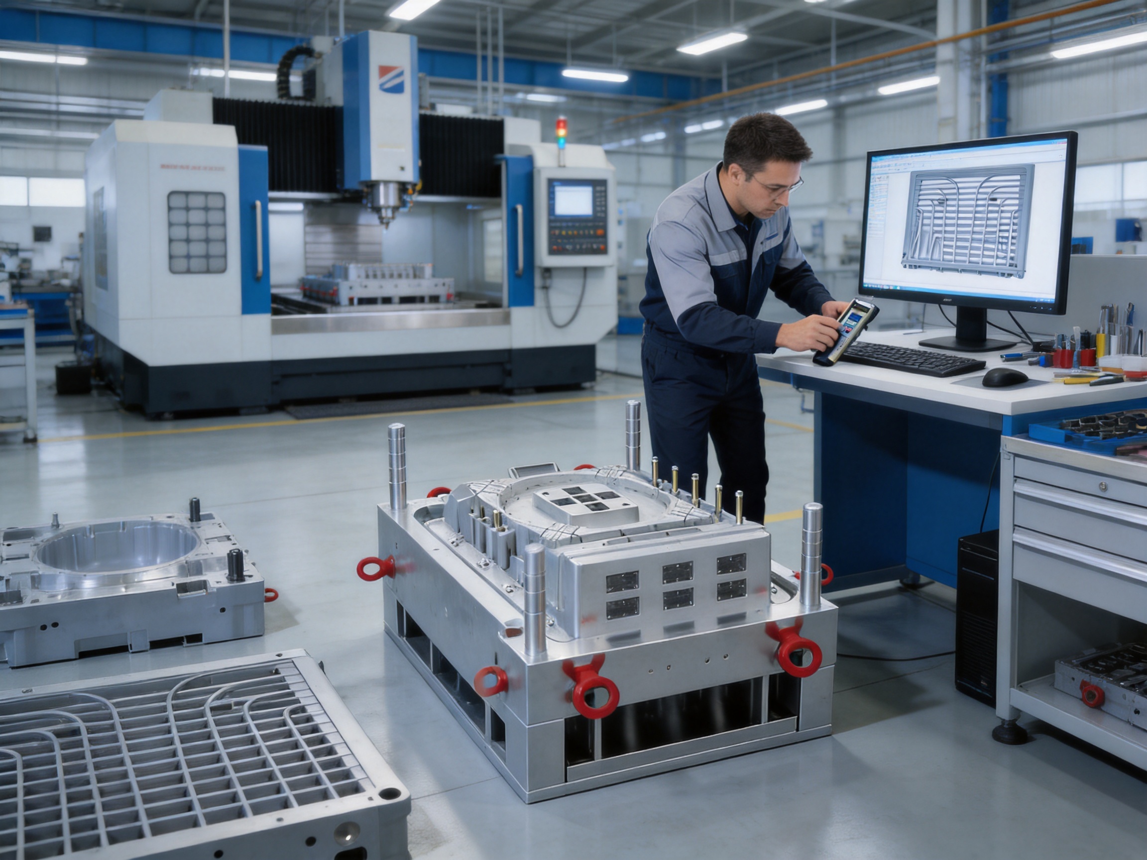
A professional design team provides support from early product review through detailed mold engineering. Computer-aided design is used to assess part construction, mold layout, component interfaces, and manufacturing feasibility. A scientific production management system helps coordinate machining, fitting, assembly, testing, inspection, and delivery.
The company’s manufacturing philosophy emphasizes quality first and sustainable development. In practical terms, this means focusing on repeatable processes, controlled production steps, clear communication, and tooling that can provide dependable service over its intended life. For international customers, these factors are important because tooling is a long-term production asset rather than a one-time purchase.
Precision Machining
Precision machining determines whether the cavity and core reproduce the intended product geometry. CNC milling, drilling, electrical discharge machining, grinding, and other operations may be selected according to the feature requirements. Tight control of machining references and inspection points helps ensure that inserts and moving components fit correctly.
Large mold bases and cavity components require particular attention to alignment. Small errors can become visible as mismatch, uneven parting lines, flash, or assembly difficulty. Accurate machining and careful fitting help maintain the relationship between cavity surfaces, sliders, lifters, ejectors, and guide elements.
Steel Selection and Tool Durability
718 and NAK80 are listed as suitable mold-steel options for this product. The final grade may be selected based on production volume, part material, surface requirements, corrosion considerations, polishing needs, and budget. Steel quality affects wear resistance, machining performance, dimensional stability, and the ability to maintain a consistent surface over repeated cycles.
Material selection should be supported by suitable heat treatment or pre-hardening conditions when required. The working surfaces, inserts, and wear components may also be planned according to the areas that experience the greatest friction or pressure. This targeted approach helps control cost while preserving durability where it matters most.
Trial Molding and Process Verification
Trial molding is used to verify whether the finished mold can produce acceptable parts under defined conditions. During the trial, engineers examine filling, packing, cooling, ejection, appearance, dimensions, assembly fit, and cycle behavior. Samples may be compared with approved drawings, reference parts, or inspection standards.
Trial results can reveal issues that are difficult to identify from computer models alone. For example, a broad surface may show unexpected warpage, a grille may require a vent adjustment, or a mounting boss may need additional support. Addressing these findings before mass production helps reduce risk for the customer.
Inspection and Documentation
Quality control should include checks of critical dimensions, cavity alignment, insert fit, moving-part operation, cooling connections, ejection movement, and surface condition. Product samples can be inspected for dimensions and visual quality, while the mold itself can be checked for correct operation and safety.
Clear documentation supports future maintenance and repeat production. Useful records may include mold layouts, steel information, spare-part details, trial parameters, inspection reports, and approved sample references. These records allow production teams to understand the tooling and respond more quickly if service is required later.
Competitive Advantages for HVAC and Appliance Manufacturers
Integrated Tooling for Housing and Functional Features
One advantage of this product is its focus on both the external housing and the structural details required for internal assembly. Some tooling solutions concentrate primarily on appearance, while others emphasize only basic dimensional output. Air cooler production requires both. The housing must look acceptable, but it must also locate components, guide airflow, withstand handling, and support fastening.
Integrating these needs into one engineering review can reduce design conflicts. Mounting bosses can be positioned in relation to ribs and cooling features. Ventilation openings can be coordinated with fan placement. Surface textures can be planned alongside draft and ejection. This whole-part approach helps produce a component that works within the complete air cooler assembly.
Adaptability to Customer Requirements
Air cooler manufacturers often produce different models for different markets. Variations may include housing width, fan size, control-panel location, water-tank capacity, handle position, grille pattern, and internal mounting arrangement. The product supports customization of component dimensions and mounting structures, allowing the tooling concept to be developed around the customer’s product architecture.
Customization is also useful when a customer wants to improve an existing product. A new mold may incorporate stronger fastening points, simplified assembly, reduced material use, improved ventilation, or a revised surface finish. Early collaboration makes it possible to consider these improvements before the design is fixed.
Balanced Investment and Production Life
Tooling costs should be considered together with expected production volume and service life. A mold with a reference life of up to 800,000 shots can be appropriate for long-running air cooler programs. When production is distributed across a large volume, the cost per molded part may become more competitive than using a lower-cost tool that requires frequent repair or replacement.
Long-term value also includes production stability. A durable mold helps maintain consistent dimensions and appearance, reducing the risk of variations between early and later production. This is particularly important when components must remain compatible with existing assembly fixtures and internal parts.
Experience Across Multiple Product Sectors
Experience in daily necessities, home appliances, automotive parts, and industrial equipment provides a broad technical foundation. Home appliance tooling requires attention to visual quality and assembly efficiency. Automotive and industrial tooling demands stronger control of dimensions, durability, and functional performance. Knowledge from these fields can be applied to the design of air cooler components.
This cross-sector experience may also help when an air cooler includes features that resemble other product categories, such as appliance-grade cosmetic panels, automotive-style clips, industrial mounting structures, or water-exposed components. A manufacturer with a broad project background can evaluate these requirements from more than one perspective.
International Service Capability
The company serves customers in Europe, the Middle East, Southeast Asia, and South America. International project experience requires attention to technical communication, packaging, delivery coordination, documentation, and after-sales support. These capabilities are important when the customer is located far from the mold manufacturing facility.
Reliable communication helps avoid misunderstandings related to units, tolerances, material grades, surface standards, mold layout, spare parts, and trial approval. A structured project process gives the customer clearer visibility from design review through final delivery.
Production Workflow from Concept to Delivery
1. Requirement Collection
The project begins with product drawings, three-dimensional files, material information, annual production estimates, machine specifications, surface requirements, and assembly details. Customers should also provide information about the intended cooling system, preferred gate locations, inspection standards, and any existing reference parts.
When some information is not yet available, the tooling team can identify open decisions and recommend practical options. Early requirement collection prevents avoidable changes after detailed mold construction has started.
2. Mold Feasibility Analysis
The product is analyzed for draft, wall thickness, undercuts, ribs, bosses, parting lines, gate positions, ejection, and cooling. Potential risks are discussed with the customer. If necessary, suggestions are made to improve moldability, reduce production cost, or simplify assembly.
For large housing components, feasibility analysis should include warpage risk and the location of critical dimensions. The customer and mold manufacturer can agree on which surfaces and interfaces require the highest level of control.
3. Mold Design Approval
After the product review, the mold structure is developed. The design may include cavity and core layouts, sliders, lifters, inserts, runners, gates, cooling channels, ejectors, guide systems, and mold-base details. The design is reviewed before machining begins.
Approval at this stage creates a common reference for the project. It allows the customer to confirm that the mold will support the intended product geometry and production method. Any design changes are easier and less costly before steel processing.
4. Steel Preparation and Machining
Selected steel is prepared for the mold base, cavity, core, inserts, and other components. Machining operations are performed according to the approved design. Critical dimensions and references are inspected during production rather than waiting until the complete mold is assembled.
Separate components are made with attention to their eventual interaction. Sliders must align with their guide systems, ejector components must move freely, and inserts must fit securely without creating unwanted steps or flash.
5. Assembly and Fitting
After machining, mold components are assembled and fitted. The team checks parting surfaces, shutoffs, moving mechanisms, ejectors, cooling connections, and overall alignment. Manual fitting remains important even when the initial machining is highly accurate because the final mold includes many interacting surfaces.
Assembly quality influences both product quality and mold life. Poor alignment can increase wear, cause flash, damage inserts, or create unsafe operating conditions. Careful fitting provides a stable foundation for trial molding.
6. Trial Molding and Corrections
The mold is tested using the intended machine conditions and product material where possible. Trial parts are evaluated for filling, appearance, dimensions, warpage, ejection, and assembly fit. Corrections may involve polishing, venting, gate adjustment, process optimization, or localized steel modification.
The objective is not only to produce one acceptable sample. The goal is to establish a repeatable production process with a reasonable operating window. Trial results should therefore be recorded and discussed with the customer before final approval.
7. Final Approval and Shipment
Once the samples and mold operation meet the agreed requirements, the tooling is prepared for shipment. Protective packaging helps prevent damage during transportation. Documentation and spare-part information can be supplied according to the customer’s needs.
After delivery, technical communication remains useful during installation and initial production. The mold manufacturer can support the customer with operating recommendations, maintenance guidance, and responses to questions that arise during production startup.
Maintenance Recommendations for Long Mold Life
Even a well-built mold requires regular maintenance. Cleaning should be performed after production, especially around vents, parting surfaces, ejector areas, and textured cavities. Resin residue, dust, oil contamination, and deposits can affect product appearance and mold movement.
Cooling channels should be monitored for blockage, corrosion, scale, and unstable water flow. Inconsistent cooling can change cycle time and product dimensions. Water quality management and periodic channel cleaning help preserve heat-transfer performance.
Moving components such as sliders, lifters, ejector pins, guide pillars, and wear plates should be lubricated with suitable products at appropriate intervals. Excessive lubrication can attract contaminants, while insufficient lubrication can increase friction and wear. The correct maintenance schedule depends on the material, cycle rate, mold environment, and production volume.
Parting surfaces should be inspected for dents, scratches, flash, or foreign material. Any damage should be addressed promptly because a small defect can grow through repeated clamping pressure. Operators should also confirm that the mold opens and closes smoothly before beginning a production run.
Maintenance records are useful for identifying patterns. If a particular ejector pin repeatedly wears, or if a specific vent requires frequent cleaning, the underlying cause can be investigated. A preventive approach is generally less expensive than waiting for an unexpected stoppage during a high-volume order.
How to Specify a Customized Air Cooler Mould
Customers preparing an inquiry should provide the product name, two-dimensional drawings, three-dimensional data, material grade, expected annual quantity, available injection machine, surface requirements, and target delivery schedule. Information about the complete assembly is also valuable because mounting features and clearances often depend on neighboring components.
The customer should identify critical dimensions, sealing areas, screw locations, snap-fit structures, visible surfaces, and areas requiring special texture or polish. If the part must fit an existing fan, motor, water tank, control panel, or frame, those interface dimensions should be clearly defined.
It is also useful to specify whether the mold will be used for one material or several materials. ABS and PP may require different process conditions and can produce different shrinkage behavior. If recycled resin, flame-retardant resin, mineral-filled resin, or other modified material is being considered, this should be communicated before the mold steel and cooling design are finalized.
Production targets influence the tooling strategy. A low-volume product may justify a simpler configuration, while a high-volume program may benefit from additional cavities, automated operation, robust inserts, replaceable wear components, or optimized cycle time. The intended production quantity should therefore be considered together with the reference mold life of up to 800,000 shots.
Quality, Efficiency, and Sustainability Considerations
Efficient molding contributes to sustainability by reducing scrap, rework, energy use per part, and unnecessary material consumption. A stable mold minimizes defective products and helps the machine operate within a controlled process window. Proper cooling design can also reduce cycle time and lower the energy required for each production cycle.
Material efficiency begins with product design. Appropriate wall thickness, rib proportions, and structural reinforcement can reduce excess plastic without compromising strength. Balanced runners and suitable gate design can limit waste, although the final choice must consider product quality and production automation.
Long mold life supports sustainability by reducing the need to manufacture replacement tooling. Durable steel, maintainable components, and replaceable wear parts can extend the productive life of the mold. Repairing selected components may be more efficient than replacing an entire mold, particularly when the product design remains unchanged.
Sustainable development also includes responsible project management. Clear specifications, organized design reviews, accurate documentation, and efficient communication help avoid unnecessary redesign and repeated machining. These practices save time and resources for both the tooling supplier and the air cooler manufacturer.
Frequently Asked Questions
What products can this injection mould produce?
The mold is designed for air cooler housings, fan covers, cooling unit components, and related plastic structural parts. The exact product range depends on the approved component design and the mold configuration.
Which materials are supported?
The listed product materials are ABS and PP. The final resin grade should be confirmed before mold design approval because different grades can have different flow, shrinkage, cooling, and surface requirements.
Can the housing dimensions be customized?
Yes. Component dimensions and mounting structures can be adjusted according to the customer’s drawings, assembly requirements, machine conditions, and production objectives.
What mold steel is available?
718 and NAK80 are identified as suitable mold-steel options. The final selection can be evaluated according to production volume, surface finish, material characteristics, wear requirements, and budget.
How long can the mold operate?
The reference mold life is up to 800,000 shots. Actual service life depends on the product design, plastic material, molding conditions, maintenance, cooling-water quality, operating practices, and repair history.
Can the mold include ventilation grilles and louvers?
Yes. Ventilation structures are part of the intended application. Their geometry should be reviewed for airflow, strength, filling, venting, draft, surface appearance, and ejection.
Can mounting bosses and internal attachment points be integrated?
Yes. Mounting features for fans, motors, control parts, water-system components, and other internal assemblies can be incorporated into the product design and mold structure.
How are large housing parts protected against warpage?
Warpage is controlled through product design review, balanced wall thickness, suitable rib design, optimized gate and runner locations, effective cooling, stable processing conditions, and controlled ejection. The precise solution depends on the geometry and resin.
What information is needed for a quotation?
Useful information includes product drawings or three-dimensional files, material, dimensions, annual quantity, surface finish, machine details, mold-life target, cavity requirements, and delivery expectations. Existing samples and assembly drawings can also improve quotation accuracy.
Does the manufacturer provide support after delivery?
The company provides integrated services covering design, production, and after-sales support. Technical communication after delivery can assist with mold installation, trial production, maintenance questions, and production optimization.
What markets does the company serve?
The manufacturer exports to Europe, the Middle East, Southeast Asia, and South America. International service experience supports communication, documentation, delivery coordination, and customer assistance.
Why is mold maintenance important for air cooler components?
Maintenance preserves dimensional accuracy, surface quality, cooling performance, and movement of mold components. Regular cleaning, lubrication, inspection, and cooling-system care help reduce unexpected downtime and protect the intended mold life.
Conclusion
The Air Cooler and Components Injection Mould is designed to support dependable production of large plastic housings, fan covers, cooling unit components, and other structural parts used in evaporative air coolers. Its application focus combines broad housing surfaces with ventilation structures and mounting features, addressing both the appearance and functional requirements of modern HVAC equipment.
Support for ABS and PP gives manufacturers flexibility in balancing rigidity, appearance, weight, chemical resistance, impact performance, and cost. The use of 718 or NAK80 steel provides a practical foundation for precision tooling, while the reference service life of up to 800,000 shots supports long-running production programs when the mold is operated and maintained correctly.
The main competitive advantages come from integrated design review, customization capability, attention to large-part molding, ventilation and mounting-feature engineering, precision machining, trial verification, and international project support. These strengths help manufacturers reduce production risk and create air cooler parts that are dimensionally consistent, visually acceptable, structurally reliable, and suitable for efficient assembly.
With professional design, scientific production management, and experience across daily necessities, home appliances, automotive parts, and industrial equipment, Taizhou Huangyan Haiquan Plastic Mold Co., Ltd. provides a complete tooling service for global customers. For manufacturers developing a new air cooler or upgrading an existing product, early cooperation with an experienced mold supplier can improve moldability, shorten project risk, and strengthen the long-term performance of the finished equipment.
References
1. Injection Molding Handbook, technical principles of thermoplastic processing, mold design, cooling, filling, and ejection.
2. Plastics Design Guidelines, general recommendations for wall thickness, draft angles, ribs, bosses, snap-fits, and molded-part manufacturability.
3. Mold Steel Selection Guide, comparative considerations for pre-hardened steels, polishability, wear resistance, and production tooling life.
4. Thermoplastic Material Data, general processing and performance characteristics of ABS and polypropylene.
5. Appliance Product Engineering Practices, design considerations for housings, ventilation structures, mounting interfaces, and consumer-equipment assembly.
6. Injection Mold Maintenance Procedures, guidance on cleaning, lubrication, cooling circuits, inspection, preventive maintenance, and service documentation.
Product: Air Cooler and Components Injection Mould

For exclusive deals and latest offers, sign up by entering your email address below.

 +86-18657672567
 sales@tzhqmould.com
celin@tzhqmould.com
 No. 17 Houshi Road, Beicheng Industrial Zone, Huangyan District, Taizhou City, Zhejiang Province, China
Copyright © Taizhou Huangyan Haiquan Plastic Mold Co., Ltd. All Rights Reserved
Injection Plastic Mould Maker

